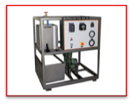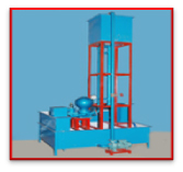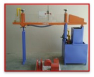


Pumps, This unit are a self-contained recirculation type unit. All the measurements are provided to evaluate the performance of the pump. The system is closed circuit. Water supplied from centrifugal pump. Rope break dynamometer is used to measure the output of turbine. Pressure Gauge and Orificemeter are used to measure the input of turbine. The system is closed circuit.
• This Pelton Turbine Test Rig 50mm size to develop 1 KW at 1000 RPM with a flow of about 450 lpm at 25
meters supply head.
• Supply pump set suitable for supplying water to the above turbine
• Monoblock Centrifugal Pump : Kirloskar Make (3 HP, 3 Phases, 440V)
• Pump Size : Suction size 65mm & Delivery size 50mm
• Pump Discharge : 420 LPM
• Delivery Head : 27 meter
• RPM : 3000 RPM
• Sump Tank: Fiber glass lined MS Tank to store sufficient water for independent circulation through
the
unit experimentation and arrange within the floor space of main unit. Capacity 300 Liter.
• Runner coupled to pelton wheel. Rope Bake Dynamometer is used to measure the output. Runner
diameter
220mm
Spring Balance 10 kg (Salter Make).
• Orificemeter of 32mm is used to measure the flow rate of water through pressure gauge difference.
Discharge control valve, by-pass valve of 50mm (ISI mark) used to control the flow rate of water.
• Pressure Gauge of 4 kg/cm2 is used to measure the pressure head.
• Rigid MS frame work compactly fitted with all the above items as a self-sufficient package unit
suitable
for operation without any foundation.
• Starter suitable for above motor pump set mounted on the control panel board.
• To determine the efficiency of Turbine.
• To draw the characteristics curve of Turbine

This is a reaction turbine and this test rig shows the construction and working of francis turbine. Rope brake dynamometer is used to measure the output of turbine. Pressure gauge and orificemeter are used to measure the input of turbine. The system is closed circuit.
• This Francis Turbine Test Rig 150mm size to develop 1 KW at 1250 RPM with a flow of about 1400 lpm at
20
meters supply head.
• Supply pump set 80x80mm size, 1500 lpm at 20 meter head suitable for supplying water to the above
turbine.
• MonoblockCentrifugel Pump : Kirloskar Make (5 HP, 3 Phases, 440V)
• Pump Size : Suction size 65mm& Delivery size 80mm
• Pump Discharge : 1200 LPM
• Delivery Head : 20 meter
• RPM : 3000 RPM
• Sump Tank:Fiber glass lined MS Tank to store sufficient water for independent
circulation through the unit experimentation and arrange within the floor space of main unit. Capacity
300 Liter.
• Rope Bake Dynamometer is used to measure the output. Spring balance and dead weights are used to
measure
the load. Runner Diameter 220mm
• Orificemeter of 53mm is used to measure the flow rate of water through pressure gauge difference.
• Discharge control valve, by-pass valve of 3" (ISI mark) used to control the flow rate of water.
• Spring Balance 25 kg &10 Kg (Salter Make)
Pressure Gauge of 4 kg/cm2 is used to measure the pressure head.
• Rigid MS frame work compactly fitted with all the above items as a self-sufficient package unit
suitable
for operation without any foundation.
• Switch and starter suitable for above motor pump set mounted on the control panel board.

This is a Kaplan turbine and this test rig shows the construction and working of Kaplan turbine. Rope brake dynamometer is used to measure the output of turbine. Pressure gauge and orificemeter are used to measure the input of turbine. The system is closed circuit.
• This Kaplan Turbine Test Rig 150mm size to develop 1 KW at 1250 RPM with a flow of about 1250 lpm at 15
meters supply head.
• Supply pump set 100x100mm size, 1500 lpm at 10 meter head suitable for supplying water to the
above
turbine.
• Monoblock Centrifugal Pump : Kirloskar Make (5 HP, 3 Phases, 440V)
• Pump Size : Suction size 80mm & Delivery size 80mm
• Pump Dischrge : 1200 LPM
• Delivery Head : 15 meter
• RPM : 3000 RPM
• Sump Tank: Fiber glass lined MS Tank to store sufficient water for independent circulation through
the
unit experimentation and arrange within the floor space of main unit.
• Capacity 300 Liter.
• Rope Bake Dynamometer is used to measure the output. Spring balance and dead weights are used to
measure
the load. Runner Diameter 220mm
• Orificemeter of 66mm is used to measure the flow rate of water through pressure gauge difference.
• Discharge control valve, by-pass valve of 4" (ISI mark) used to control the flow rate of water.
• Spring Balance 25 Kg & 10 Kg (Salter Make)
Pressure Gauge of 4 kg/cm2 is used to measure the pressure head.
• Rigid MS frame work compactly fitted with all the above items as a self-sufficient package unit
suitable for operation without any foundation.
• Switch and starter suitable for above motor pump set mounted on the control panel board.
• To determine the efficiency of Turbine
• To draw the characteristics curve of Turbine.

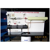
• The Test Rig provided study of a Steam Turbine.
• With the help of various measurement provided.
• Steam Ganreting tank.
• Pressure Gauge to measure Pressure.
• Multi-channel Digital Temperature Indicator: to measure the temperature at various points.
• Chamber for Steam

Centrifugal pump are Dynamic Pressure Pumps. This unit is a self-contained recirculation type unit. All the measurements are provided to evaluate the performance of the pump. The system is closed circuit.
• Centrifugal pump of 25x25mm coupled to 1 H.P. A.C. motor (1400 RPM).
• Sump tank of size 80 Ltr.
• Discharge measurement tank of size 30 Ltr.
• Pressure Gauge, Range: 0-4 Kg/cm2
• Vacuum Gauge, Range: 0-760 mm/hg
• Control Valve to control discharge.

Reciprocating double acting Pumps are positive displacement pumps. This unit is a self-contained recirculation type unit. All the measurements are provided to evaluate the performance of the pump. The system is closed circuit.
• Reciprocating pump of 25x25mm coupled to ½ H.P. A.C. motor (1400 RPM).
• Sump tank of size80 Ltr.
• Discharge measurement tank of size 30 Ltr.
• Pressure Gauge, Range: 0-4 Kg/cm2
• Vacuum Gauge, Range: 0-760 mm/hg
• Control Valve to control discharge.
• Electronic Energy meter
• DPDT Switch
• To determine the efficiency of pump.
• Discharge V/s Total head
• Discharge V/s Input power
• Discharge V/s Output power
• Discharge V/s Efficiency of pump
• Discharge V/s Overall efficiency

The Hydraulic Ram is a pump which rise the water without any external power for its operation when large quantity of water is available at a small height, a small quantity of water can be raised to a greater height with the help of hydraulic ram. This works on the principle of water hammer. The system is closed circuit.
• It consists of a suitable size centrifugal pump 2 H.P. A Motor to make the supply from sump tank to
supply tank. This apparatus consists of fiber coated MS sump tank of suitable capacity. Supply Tank:
• Fiber coated MS tank fixed on angle frame & Capacity 150 Liter.
• Measuring tanks: Two fiber coated MS tank fitted with piezometric tube to measure the waste water
and
useful water.
• Air vessel is provided to perform the phenomena of water hammer.
• A pressure
gauge is
fitted on useful water pipe line to measure the head of water.
• To determine the following efficiency of hydraulic ram:
• Rankine's efficiency
• D'Aubuisson's efficiency
• To find the cavitations number of the flow.

The hydraulic flume should be of size 150mm depth x 250mm wide x 4 meter length built with extra strong
75mm x 50mm. Thickness 4mm through. MS channel b for strength and rigidity. Both vertical sides provided
with transparent thick 6mm Perspex for flow visualization at least for 4 meter length. The 16 gauge M.S.
Sheet nearly fixed to MS angle frame with rubber packing. The upstream and downstream sections provided
with two numbers of fine gates with rack (GM) pinion arrangement for accurate and smooth operation to
facilitate the varying the discharge and head water. The sides provided with inverted Tee section (MS)
for smooth running of movable hook gauge trolley. The tilting arrangement provided with a fine
arrangement which can be operated very smoothly. The slope of the flume ranges up to +5 degree. The
tilting arrangement operated by both forward and backward slope settings. For hydraulic different types
of experiments the accessories should be incorporated like
• Water tank capacity of size 200 Ltr.
• Discharge measurement tank of size 50 Ltr.
• Monoblock Centrifugal Pump 2 HP, 3 Phases (Kirlosker Make)
• Hook gauge 30cm length fitted on a trolley & arrangement for transverse and longitudinal movement
should
be supplied. Pipe line to carry water to flume and foot valve at suction end provided.
Centrifugal pump set for supplying water to the flume provided with epoxy painted inside to prevent rust
hence increase the life of tank for total rust protection.
1. To determine Co-efficient of roughness n for a given flume.
2. To calibrate a broad-crested weir and study the pressure distribution at the upstream end of the
weir.
3. To study characteristics of Hydraulic Jump.
4. To calibrate a vertical fall and to study the effect of cistern length on the energy
dissipation.

a) Length of wind tunnel - 3.5m.
b) Axial flow fan and the duct - 1.1m long
c) Maximum height - 2.0m
d) Test solution - 30cm x 30cm cross-section and 100cm length
e) Air speed - 20mps
f) Motor for axial flow fan – 3HP, AC motor.
g) Speed Control for AC Motor.
h) Blades of fan shall be made of Aluminum cast aerofoil